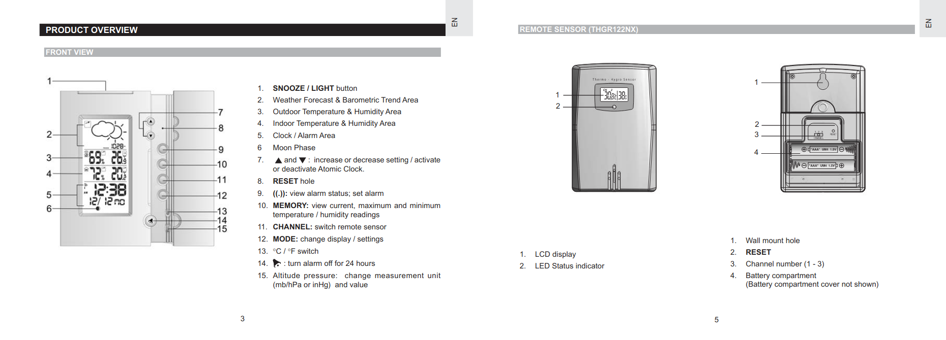
I have a digital clock, made by Oregon Scientific, that displays temperature and humidity readings transmitted to it by a sensor that lives outside. The receiver has held up well over the 17 or 18 years I’ve had it, but I’ve had to replace the remote sensor, constantly exposed to the elements as it is, several times.
Years ago, the specific sensor model compatible with my base station was easy to buy and not too expensive. Now, though, it’s hard to find at a price justifiable for such an old clock, if at all. When I bought the last replacement in 2018, it cost $55 on Amazon (I could buy a whole new weather station for about that price, but what a waste). At least it was available. Today, I can only find one eBay listing for a well-used, untested, $95 sensor, and this neat British shop, which at time of writing lists a couple compatible new sensors as “back soon”. Even if they were in stock, once shipping to Canada and duties were factored in, a replacement sensor would cost over $100.
Thus, before the sensor I have stops working, I wanted to characterize the signal it transmits and figure out how to reproduce it. I thought it would be far easier to do so while I still had a reference sensor to compare to.
I did some poking around on the Internet and found that there’s actually quite a large body of knowledge on the protocols used by remote weather sensors– it seems like a lot of people buy them separately to use with custom-built Arduino, Raspberry Pi, or PC-based receivers. The most complete (and most frequently referenced) source of information I found is osengr.org, home to an open-source Arduino-based receiver that supports a wide range of sensors from various manufacturers. This 45-page PDF (also rehosted here) is the fourth in a series of successively more expansive documents comprehensively describing all kinds of weather sensor protocols, including the one used by the THGR122NX sensor my base station came with. Kudos and many thanks to the author.
Armed with a 433 MHz transmitter and DHT-22 temperature/humidity sensor from AliExpress and an Arduino, I set about naïvely implementing a clone of my sensor based purely on my interpretation of the description of the Oregon Scientific v2.1 RF protocol from the PDF. Perhaps inevitably, it didn’t work (does implementing something right from the spec ever work on the first try?).
To debug my failed transmission attempt, I needed some way to record the signal and compare it to the one transmitted by the real sensor. Here is a photo of me at the moment I came to that realization:

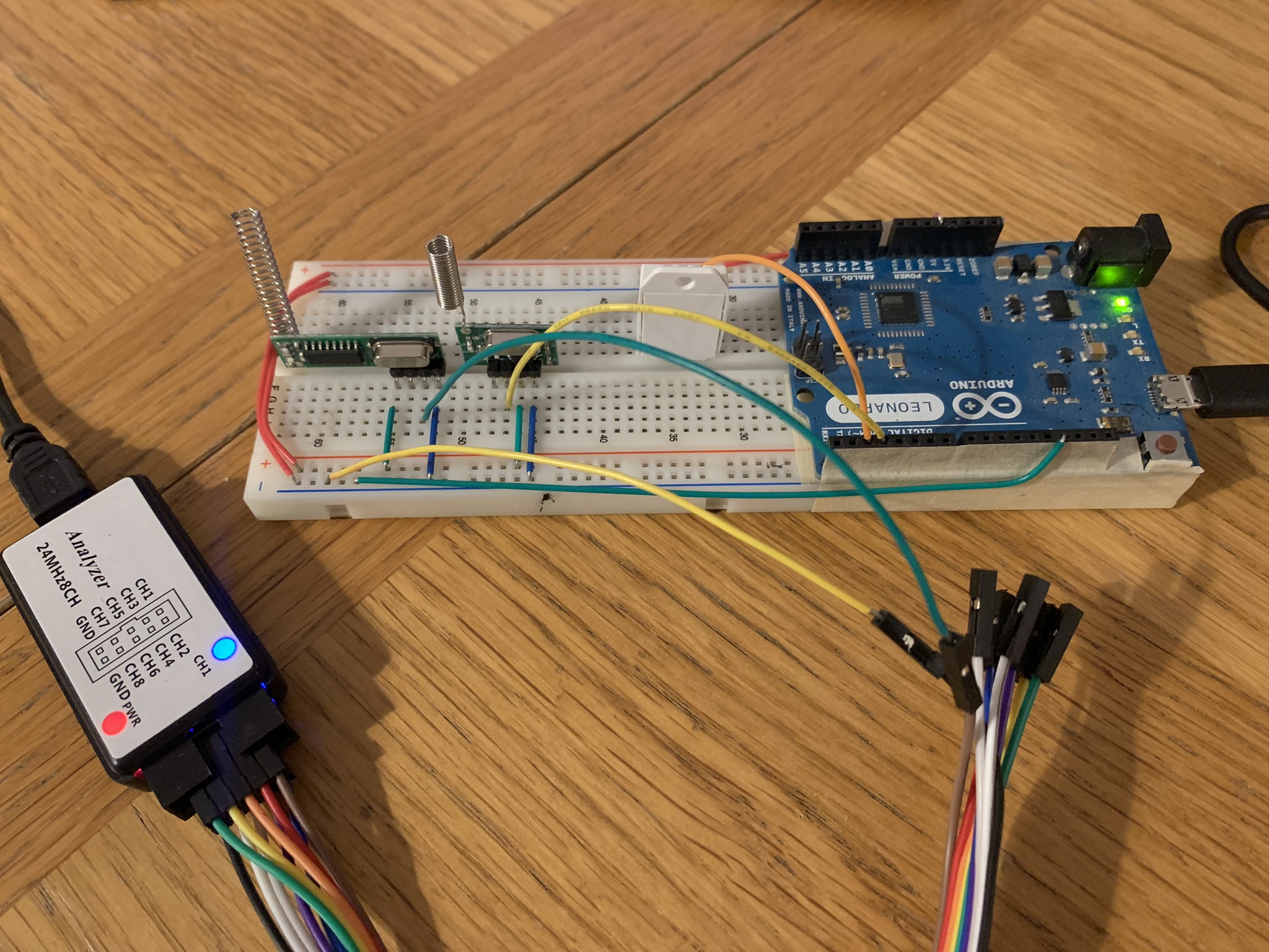
I did some reading and found out that what I needed was called a logic analyzer, which is like an oscilloscope, but for digital signals and capable of recording signals over time. At the recommendation of this video introduction to logic analyzers and Sigrok, an open-source signal analysis software suite including a GUI called PulseView, I bought a $20 USB logic analyzer from Amazon (also available for like $6 on AliExpress, but I was impatient). The analyzer, which is a Chinese clone of a discontinued professional-grade tool made by Saleae, supports 8 channels and can capture 24 million samples per second. The fact that such a useful tool is available for so cheap boggles my mind– what a time to be alive.
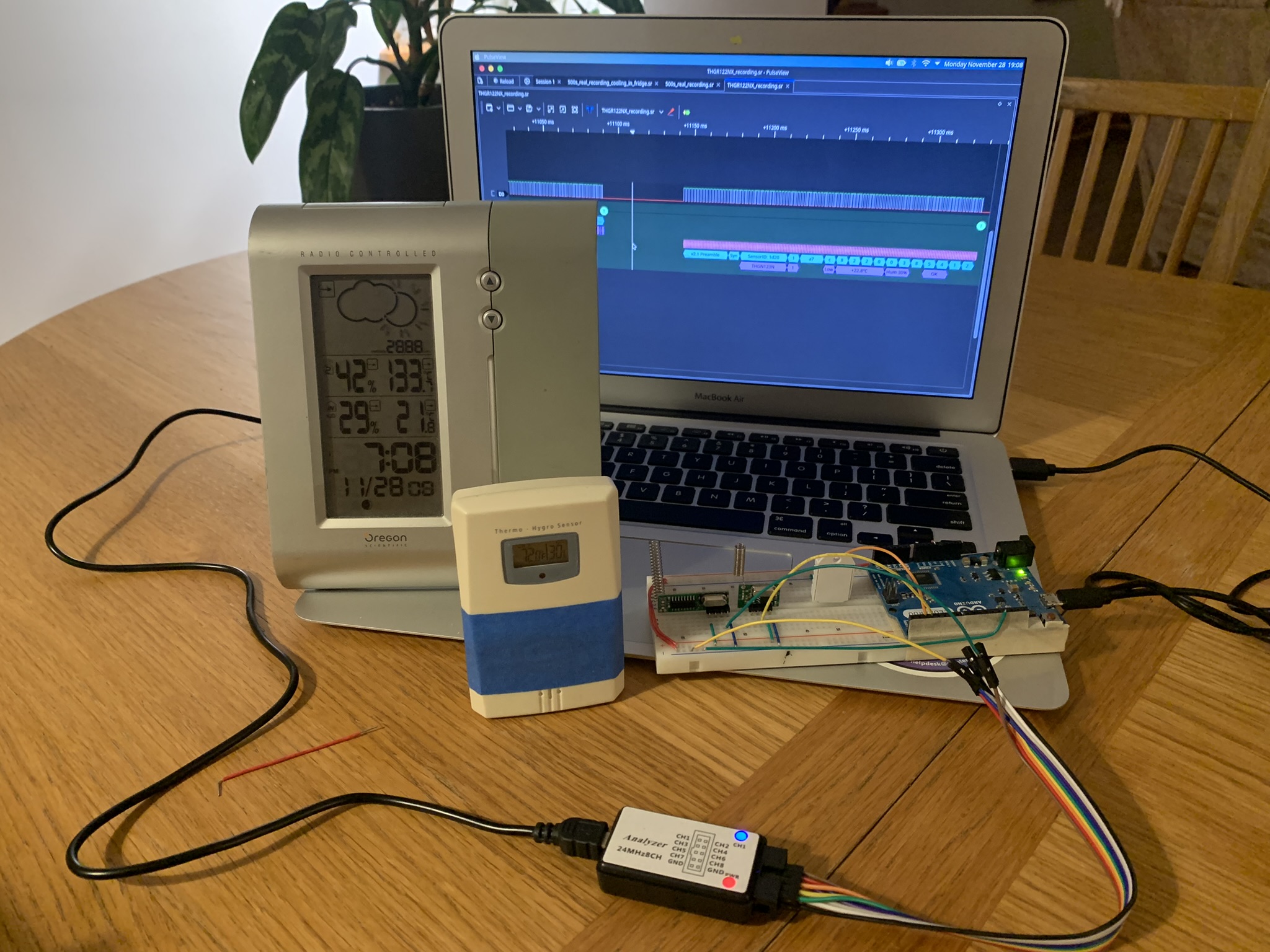
I plugged a 433 MHz receiver into one of the leads of the logic analyzer and captured some recordings of transmissions from the real sensor. I had expected to have to do a lot of squinting at square waves and pencil/paper work to decode the signal, but while looking through the menu of built-in decoders for one that could take some of the work out of reading the Manchester-encoded signal, I discovered that not only did the built-in On-Off Keying decoder support decoding Manchester code, but that there was also a second-level decoder specifically for the various Oregon Scientific protocols. What a time saver!

After much trial and error, I came up with the following protocol description and a working prototype.
THGR122NX protocol description
The osengr PDF promises “descriptions … sufficient for those building maker projects to receive and decode these signals”; based on my experimentation, here’s a full description of the Oregon Scientific v2.1 protocol as implemented by the THGR122NX sensor, sufficient for transmitting a signal that will be accepted by an original Oregon Scientific base station. Some information may be applicable to other sensors that implement the v2.1 protocol.
Carrier wave and bit encoding
Bits are transmitted at 1024 Hz using normal-mode Manchester coding on a 433.92 MHz carrier wave. The 433.92 MHz wave can be generated or demodulated into a simple digital signal by specialized hardware like the cheap transmitter and receiver pair linked above. Manchester code uses a transition at the middle of each clock cycle to indicate a bit value: in the normal mode, a 0 is encoded as off-on and a 1 as on-off (in the reversed mode, it’s the opposite). This graphic from Wikipedia shows how it works:

For protocol v2.1, each bit is sent twice, but inverted the first time. So, for example, the bit sequence 1011 is actually transmitted as 01100101, which, in Manchester coding, becomes off-on-on-off-on-off-off-on-off-on-on-off-off-on-on-off, with each on or off state held for (1/1024)/2 seconds. The entire sequence is then repeated, after a short delay of 10.9 ms according to the PDF, or about 55 ms based on my observations. Since we both apparently used THGR122NX sensors, we can probably conclude that the specific length of the delay doesn’t matter.
As you can see from the example above, in this scheme, a transmission is composed of intervals where the signal is either on or off for either a long or short time (depending on whether adjacent half-cycles are the same state). In the PDF, the author describes a sensor which always cuts short the on pulses by a consistent amount. My sensor didn’t exhibit the same behaviour: rather, the duration of individual on and off pulses varied wildly, but the average clock rate was still almost precisely 1024 Hz.
The Oregon Scientific receiver is very picky about the clock rate of the signal; any more than a few microseconds off per cycle and it’ll ignore the transmission. I found that if I used Arduino’s delayMicroseconds function to pause for 488 μs between state changes, the resulting RF pulses were actually too long for the receiver. Thus, the nominal delay must be callibrated depending on the hardware generating the signal so that the real signal is clocked as closely as possible to 1024 Hz (976.5 μs per cycle). This is mentioned by readers in the comments on this blog post, in which the author, Olivier Lebrun, described a simulated v2.1 sensor that could be picked up by an aftermarket base station; as the commenters there and my experience can attest, the original base stations are pickier about timing.
Data format
V2.1 protocol data frames vary in length between sensor models. There are more details on other sensors in the osengr PDF; here’s the format of the data transmitted by my THGR122NX sensor.
Each frame is 96 bits long, divided into 24 nibbles. The nibbles are transmitted in order, with each one transmitted least-significant-bit-first; e.g. the nibble 0x8 (1000 in binary) would be transmitted as 0, 0, 0, 1.
0-3: The first four nibbles are a pre-amble consisting of 161bits. Recall that each bit is transmitted twice, inverted first, so really this results in a transmission of01010101010101010101010101010101. This is used to alert the receiver that a message is incoming and to give its automatic gain control circuit a chance to callibrate itself to the signal strength. In theory, it also allows a receiver to recover the clock rate of the signal, but the Oregon Scientific base station doesn’t do that.4: The sync nibble (0xa) identifies where the pre-amble ends and where the message payload begins.5-8: The sensor ID, which varies between sensor models. For the THGR122NX and apparently some other functionally equivalent models, the ID is, in the order of transmission,0x1,0xd,0x2,0x0.9: The channel number, either 1, 2, or 3, but encoded as0x1,0x2, or0x4(i.e. the first, second, or third bit in the nibble).10-11: The rolling ID, which is a random identifier generated when the batteries are inserted.12: Flags. The battery-low flag is0x4. I also observed the0x8bit set far more often than not, regardless of the presence of the battery-low flag and regardless of the current temperature and humidity. It doesn’t appear to mean anything. The PDF mentions that one status bit might change between the first and second repetitions of the signal, but I did not observe that behaviour from my sensor.13-16: The temperature in degrees Celcius, represented in binary-coded-decimal with the 0.1s first, then the ones, then the tens, then the hundreds. The largest bit of the fourth nibble represents the sign (0x0for positive and0x8for negative).17-18: The relative humidity, with ones transmitted in the first nibble and tens in the second.19: Always0x8, meaning unknown.20-21: A checksum calculated by adding together all the nibbles from5-19, inclusive. Any time overflow occurs during this summation (i.e. the sum is greater than 255 or what fits in 1 byte), it’s added back into the result. Transmitted in LSB-first order.22-23: A second checksum, calculated by the CRC-8-CCITT algorithm described in the PDF, but with an initial value of0x42and considering only nibbles5-9and12-19. Transmitted in LSB-first order.
CRC
More on the CRC (which stands for cyclic redundancy check)… I had got to a point where I could reliably replay signals captured from my real sensor and have them be picked up by the receiver, but I wasn’t yet able to transmit arbitrary data because I couldn’t generate a valid CRC. Part of implementing the CRC algorithm is picking an initial value for the result register. According to the PDF, version 3 sensors use an initial value of zero, and
Version 2.1 sensors appear to use different initial register values – even among sensors of the same model. It is not clear if this is actually correct – it seems a little odd to ask the receiver of these messages to figure out the correct initial register value. Perhaps there is a simpler explanation for the CRC algorithm used in version 2.1 sensors.
In Olivier’s blog post, he didn’t address the CRC byte; transmitting two zero nibbles in its place was good enough since the aftermarket receiver he was targeting didn’t verify the secondary checksum anyway. One commenter provided an implementation of a function to generate the CRC, and a couple others indicated that they were able to get it to work with real base stations by using different initial values, which lines up with what the PDF said.
The initial value is just the value stored in the result register before any of the message bits have been fed into the algorithm. Knowing that there must be some way to deterministically calculate the CRC without having any advance knowledge about the specific sensor sending the message, I reset my sensor a bunch of times and recorded the subsequent transmissions to see if I could figure out the pattern. Since there are only 255 possible values for the IV, it’s trivial to determine it by brute force for any given transmission, based on the actual CRC. As expected, the IV did appear to be consistent between transmissions but change with each sensor reset, along with the rolling ID.
The key insight in figuring out how the CRC worked came when I noticed that even when the rolling ID changed, as long as the other data in the transmission remained constant, the CRC stayed the same. That could only mean that however the sensor was calculating the CRC, the rolling ID was not involved.
By calculating the CRC using nibbles 5 to 19, inclusive, but excluding the rolling ID nibbles, I found that the initial value could be assumed to be a constant, 0x42. Perhaps there is an even simpler explanation than that, but, since this seems to work even when varying the rolling ID and changing the channel number, I’ll take it.
Prototype
What’s next?
The prototype proves that it works; my next step is to build a more practical sensor based on an ATTiny85 microcontroller, which will be much cheaper than a full-size Arduino board, use far less power, and fit in a tiny plastic case. I’ll link it here when it’s done. EDIT: ATtiny85-based Oregon Scientific v2.1 remote temperature sensor
The code
sensor.ino:
1
/*
2
* Arduino-based temperature/humidity sensor compatible with the Oregon Scientific v2.1
3
* 433.92 MHz weather sensor protocol.
4
*
5
* This sketch replicates the behaviour of the Oregon Scientific THGR122NX sensor.
6
*
7
* More info here: https://shumphries.ca/blog/2022/12/04/oregon-scientific
8
*
9
* LICENCE
10
*
11
* Copyright © 2022 Stephen Humphries
12
*
13
* Permission is hereby granted, free of charge, to any person obtaining a copy
14
* of this software and associated documentation files (the "Software"), to deal
15
* in the Software without restriction, including without limitation the rights
16
* to use, copy, modify, merge, publish, distribute, sublicense, and/or sell
17
* copies of the Software, and to permit persons to whom the Software is
18
* furnished to do so, subject to the following conditions:
19
*
20
* The above copyright notice and this permission notice shall be included in all
21
* copies or substantial portions of the Software.
22
*
23
* THE SOFTWARE IS PROVIDED "AS IS", WITHOUT WARRANTY OF ANY KIND, EXPRESS OR
24
* IMPLIED, INCLUDING BUT NOT LIMITED TO THE WARRANTIES OF MERCHANTABILITY,
25
* FITNESS FOR A PARTICULAR PURPOSE AND NONINFRINGEMENT. IN NO EVENT SHALL THE
26
* AUTHORS OR COPYRIGHT HOLDERS BE LIABLE FOR ANY CLAIM, DAMAGES OR OTHER
27
* LIABILITY, WHETHER IN AN ACTION OF CONTRACT, TORT OR OTHERWISE, ARISING FROM,
28
* OUT OF OR IN CONNECTION WITH THE SOFTWARE OR THE USE OR OTHER DEALINGS IN THE
29
* SOFTWARE.
30
*/
31
32
#include <DHT.h> // Adafruit's DHT sensor library (https://github.com/adafruit/DHT-sensor-library)
33
// This library and/or the DHT-22 sensor can trivially be swapped out as required
34
35
#define DHT_PIN 2 // I/O for the temperature/humidity sensor
36
#define TX_PIN 3 // Output for the 433.92 Mhz modulator
37
38
#define SHORT 478 // Half of 1/1024 (which is about 488 us), but calibrated for real time (hardware dependent)
39
// If you don't have an oscilloscope or logic analyzer handy, you could probably dial it in
40
// by trying values from 470 to 500 or so
41
42
#define SUM_MASK 0xfffe0 // Only some nibbles are included in the checksum and CRC calculations
43
#define CRC_MASK 0xff3e0
44
#define CRC_IV 0x42 // ¯\_(ツ)_/¯ (see the blog post for details)
45
#define CRC_POLY 0x7 // CRC-8-CCITT
46
47
// Example transmission data
48
// - Bytes are transmitted in order, small nibble first
49
// - Nibbles are transmitted LSB-first
50
// - Nibble descritions in this example are large nibble first, to align with the byte-wise representation
51
// - Sensor ID 1d20, Channel 1, Rolling ID bb, Battery low, Temperature 22.7°C, Humidity 30%
52
// uint8_t data[] = {
53
// 0xff, // Preamble (16 ones (transmitted as 32 bits, alternating 01))
54
// 0xff, // Preamble
55
// 0x1a, // Sensor ID (1d20) / Sync (0xa)
56
// 0x2d, // Sensor ID
57
// 0x20, // Channel (1=0x1, 2=0x2, 3=0x4) / Sensor ID
58
// 0xbb, // Rolling ID (randomly generated on startup)
59
// 0x7c, // Temperature, 10^-1 / Battery low (low is 0x4, not low is 0x0, but both are often OR'd with a 0x8 bit of unknown significance)
60
// 0x22, // Temperature, 10^1 / Temperature, 10^0
61
// 0x00, // Humidity, 10^0 / Temperature sign (largest 2 bits, 0x0 for +ve, 0x8 for -ve) | Temperature 10^2 (smallest 2 bits)
62
// 0x83, // Unknown / Humidity, 10^1
63
// 0x4a, // Checksum (simple sum)
64
// 0x55, // Postamble (CRC checksum)
65
// };
66
67
uint8_t data[] = { // Data frame, initialized with the parts that never change
68
0xff, // Preamble
69
0xff,
70
0x1a, // Sync nibble and sensor ID
71
0x2d,
72
0x00,
73
0x00,
74
0x08, // Unknown
75
0x00,
76
0x00,
77
0x80, // Unknown
78
0x00,
79
0x00,
80
};
81
int dataLen = 12;
82
83
DHT dht = DHT(DHT_PIN, DHT22);
84
85
void setup() {
86
dht.begin();
87
88
pinMode(TX_PIN, OUTPUT);
89
randomSeed(analogRead(0));
90
91
data[4] &= 0x0f; data[4] |= ((0x1 << 4) & 0xf0); // Channel, 1=0x1, 2=0x2, 3=0x4 // TODO: Read channel from pins?
92
data[5] &= 0x00; data[5] |= (random(256) & 0xff); // Rolling ID
93
}
94
95
void loop() {
96
float t = dht.readTemperature();
97
uint8_t t_sign = t < 0;
98
uint8_t t_deci = ((int)(t * (t_sign ? -10 : 10)) / 1) % 10;
99
uint8_t t_ones = ((int)(t * (t_sign ? -10 : 10)) / 10) % 10;
100
uint8_t t_tens = ((int)(t * (t_sign ? -10 : 10)) / 100) % 10;
101
uint8_t t_huns = ((int)(t * (t_sign ? -10 : 10)) / 1000) % 10;
102
103
float h = dht.readHumidity() + 0.5; // Round to the nearest one by adding 0.5 then truncating the decimal
104
uint8_t h_ones = ((int)(h * 10) / 10) % 10;
105
uint8_t h_tens = ((int)(h * 10) / 100) % 10;
106
107
// data[6] &= 0xf8; data[6] |= (lowBattery() ? 0x4 : 0x0); // Not implemented
108
109
data[6] &= 0x0f; data[6] |= ((t_deci << 4) & 0xf0);
110
data[7] &= 0xf0; data[7] |= ((t_ones << 0) & 0x0f);
111
data[7] &= 0x0f; data[7] |= ((t_tens << 4) & 0xf0);
112
data[8] &= 0xfc; data[8] |= ((t_huns << 0) & 0x03);
113
data[8] &= 0xf3; data[8] |= ((t_sign << 3) & 0x0c);
114
115
data[8] &= 0x0f; data[8] |= ((h_ones << 4) & 0xf0);
116
data[9] &= 0xf0; data[9] |= ((h_tens << 0) & 0x0f);
117
118
data[10] &= 0x00; data[10] |= (checksumSimple(data, SUM_MASK) & 0xff);
119
data[11] &= 0x00; data[11] |= (checksumCRC(data, CRC_MASK, CRC_IV) & 0xff);
120
121
sendData(data, dataLen);
122
123
delay(40000);
124
}
125
126
127
void sendData(uint8_t data[], int len) {
128
for (int i = 0; i < 2; ++i) { // Send the message twice
129
cli(); // Disable interrupts to avoid any timing funny business
130
for (int j = 0; j < len * 8; ++j) { // Bits are transmitted LSB-first
131
sendBit((data[j / 8] >> (j % 8)) & 0x1);
132
}
133
digitalWrite(TX_PIN, LOW); // Don't leave the transmitter on!
134
sei(); // Re-enable interrupts
135
delay(55); // Pause for a short time between transmissions
136
}
137
}
138
139
void sendBit(bool val) {
140
if (val) {
141
sendLowHigh();
142
sendHighLow(); // Doing it this way keeps the timing consistent, though
143
} else { // any difference is probably negligible
144
sendHighLow();
145
sendLowHigh();
146
}
147
}
148
149
void sendLowHigh() {
150
digitalWrite(TX_PIN, LOW);
151
delayMicroseconds(SHORT);
152
digitalWrite(TX_PIN, HIGH);
153
delayMicroseconds(SHORT);
154
}
155
156
void sendHighLow() {
157
digitalWrite(TX_PIN, HIGH);
158
delayMicroseconds(SHORT);
159
digitalWrite(TX_PIN, LOW);
160
delayMicroseconds(SHORT);
161
}
162
163
uint8_t checksumSimple(uint8_t data[], uint64_t mask) {
164
uint16_t s = 0x0000;
165
166
for (int i = 0; i < 64; ++i) {
167
if (!((mask >> i) & 0x1)) continue; // Skip nibbles that aren't set in the mask
168
169
s += (data[i / 2] >> ((i % 2) * 4)) & 0xf; // Sum data nibble by nibble
170
s += (s >> 8) & 0x1; // Add any overflow back into the sum
171
s &= 0xff;
172
}
173
174
return s;
175
}
176
177
uint8_t checksumCRC(uint8_t data[], uint64_t mask, uint8_t iv) {
178
uint16_t s = iv;
179
180
for (int i = 0; i < 64; ++i) {
181
if (!((mask >> i) & 0x1)) continue; // Skip nibbles that aren't set in the mask
182
183
uint8_t nibble = (data[i / 2] >> ((i % 2) * 4)) & 0xf;
184
185
for (int j = 3; j >= 0; --j) {
186
uint8_t bit = (nibble >> j) & 0x1;
187
188
s <<= 1;
189
s |= bit;
190
191
if (s & 0x100) {
192
s ^= CRC_POLY;
193
}
194
}
195
}
196
197
for (int i = 0; i < 8; ++i) {
198
s <<= 1;
199
if (s & 0x100) {
200
s ^= CRC_POLY;
201
}
202
}
203
204
return s;
205
}