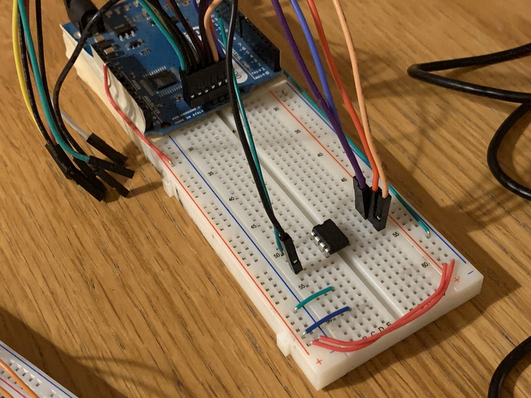
In my last post, I showed off a prototype of my Arduino-based Oregon Scientific v2.1 sensor. It worked, but it wouldn’t be very practical for real use. Let’s take a look at building a more “production-ready” version. The following headers are in no particular order; a wiring schematic (if you can call it that) is near the bottom of the post, and so is the code.
Bill of materials
- ATTINY85V-10PU
- 1″ × 1″ perfboard
- 433 MHz transmitter
- DHT22 sensor
- 2x 100 nF capacitor
- 32 768 Hz crystal oscillator
This comes out to about $10 CAD if you ignore my wasted shipping costs from placing multiple orders, the fact that I actually bought several of each part, and the large Amazon markup I paid to get a box of several hundred capacitors shipped next-day rather than waiting for delivery from China.
Microcontroller
The Arduino-on-breadboard form factor, while great for prototyping, is too expensive (25 USD for an Arduino Leonardo), too large (2.7″ × 2.1″ just for the board itself), and too power-hungry (it draws ~20 mA at 3.3 V running an empty Arduino sketch at 16 MHz) to use for something as simple and portable as a temperature sensor.
I chose an ATtiny85 microcontroller as the brain for version 2 of my sensor since it’s compatible with the Arduino IDE and my existing code but tiny (so accurately named!) and cheap. A 1″ square perfboard provides a perfect platform for the 8 pin chip and the the few necessary peripherals.
Programming the ATtiny85
I programmed the ATtiny85 using my Arduino Leonardo board and the ArduinoISP sketch included with the Arduino IDE. It’s easy to find instructions on how to do this, e.g. here.
Power consumption
Out of the box, an Arduino board running a naïvely written sketch can be impractical to run on battery power: assuming a capacity of 1200 mAh per AAA cell, a constant load of 20 mA (as quoted above for an empty sketch running on an Arduino Leonardo at 16 MHz and 3.3 V) would drain two cells in only about 5 days. Nick Gammon describes some ways to save power in microcontroller projects here. Based on those tips, I chose to:
- lose the development board and just use a microcontroller on its own,
- disable the Analog to Digital converter when not in use,
- use as low a clock speed as possible,
- power off peripherals (sensor, radio, oscillator) when not in use, and
- rarely busy-wait; use the microcontroller’s power-off sleep mode whenever possible.
I configured the ATtiny to run at 8 MHz, instead of 16, which saves a significant amount of power when the CPU is running. The microcontroller’s internal oscillator can also run at 1 MHz, but that’s too slow to interface with the DHT22 sensor, at least with the library I was using.
Powered on but not transmitting, the 433 MHz transmitter draws about 4.7 mA; transmitting, this jumps to 25.5 mA. The DHT22 draws about 170 µA at idle and a few mA when in use. The oscillator also draws a few µA when powered on. All of these would reduce battery life if they were powered on all the time, so I elected to switch them on only when necessary. Since each pin on the ATtiny can supply 40 mA, it’s fine to drive the peripherals directly.
In power-off sleep with all the peripherals unpowered and the ADC disabled, I found that the ATtiny85 uses only about 4.4 µA at 3.3 V. This is basically a rounding error compared to the power usage when not sleeping: ~4 mA by the microcontroller itself when the processor is running for a fraction of a second, plus 25 mA for 0.2 seconds when transmitting (the signal takes about 0.2 seconds to send and we send it twice; given a 50% duty cycle that means the transmitter is powered for 0.2 seconds). Plugging those rough numbers into a calculation indicates that two AAAs should power the device for at least a year and a half.
Timing
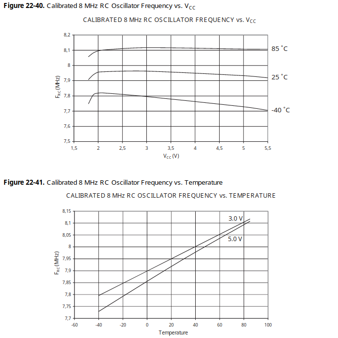
I mentioned in my previous post that the Oregon Scientific base station is very picky about timing– if the average clock cycle length in a transmission is off by more than ±3 µs from the nominal length of ~976.5 µs, the transmission will be ignored. That’s a tolerance of only about 0.3%, which I met in the prototype by calibrating the delay used to generate the output signal based on the signal’s measured frequency. Unfortunately, the ATtiny85’s internal RC oscillator is not particularly stable with respect to voltage or temperature, both of which will vary in this application as the battery wear and weather conditions change. According to the datasheet (which was an invaluable resource at every step of this build), the frequency can vary by nearly 4%, an order of magnitute more what would be acceptable. When I tested this by putting my ATtiny-based v2 prototype, which worked fine at room temperature, in the freezer, the base station quickly stopped receiving transmissions and the recordings that I captured on my laptop confirmed that the signal’s frequency had dropped well out of spec.
I toyed with the idea of trying to model the expected internal oscillator frequency based on the instantaneous measured temperature and voltage, but it seemed very unlikely that the results would be precise enough to be worth the effort. The consensus on AVRFreaks.net when somebody else considered doing something similar was that, “unless your widget will be produced by ten of millions pieces a year”, “do not fuck your brain … connect a crystal to it”. Sage advice. Instead, I ordered a 32 768 Hz crystal oscillator, guaranteed to be accurate to ±20 ppm (parts per million) at room temperature and up to an additional 150 ppm off at the extremes of -40°C to 90°C. That’s an order of magnitude tighter than the receiver requires. 🙌
The ATtiny85 supports clocking the entire device with an external oscillator or crystal. Higher-frequency crystals use more power, though, and, in this case, I don’t care what frequency computations are performed at anyway. That’s why, instead of replacing the device clock source, I opted to use a crystal oscillator with a frequency divisible by 2 × 1 024 Hz as the clock source only for Timer0, leaving the CPU to use the imprecise internal oscillator. I rewrote the signal generation code to use sleeps and interrupts (occurring every 16 ticks of the 32 768 Hz oscillator, i.e. at 2 048 Hz) to generate the output signal. This resulted in an acceptable level of precision over the whole voltage and temperature range.
Aside: why 32 768 Hz?, you might ask. Well, 32 768 is divisible by 2 048, so it’s a suitable frequency for this particular task, which requires a 1 024 Hz output signal. Secondarily, 32 768 Hz crystal oscillators are extremely abundant and cheap because they’re commonly used in real-time clock applications (like almost all digital watches)– you can measure exactly 1 second using a 32 768 Hz oscillator and a 15-bit binary counter.
The watch crystal worked well, but I misread the datasheet when ordering it and was unpleasantly surprised to find that it was only 2 mm² in area. This crumb-sized component proved very difficult to solder onto my perfboard; I ended up having to place it at an angle to get three of the pins touching solder pads, then use a glob of solder between the fourth pad and metal lid to establish the ground connection. If I ever build another one of these, I’ll design a real PCB with properly spaced pads.
Irrational temperature data
I noticed that once in a while, particularly when testing it in the freezer, my DHT22 sensor returns irrational data: either 150°C/100% RH or 50°C/0% RH. I’m not sure why this happens; maybe it’s just a bad part. The datasheet doesn’t mention anything about these values, but I ordered the sensor from Aliexpress so who knows if it’s even the real thing. Anyway, I added a check for these specific pairs that causes the program to leave the sensor powered on for a couple seconds then try again. This seems to usually result in a successful reading.
Low-battery detection
I didn’t bother to implement low-battery detection in my earlier prototype, but the v2.1 protocol does support a low-battery flag. The ATtiny85 can use its Analog to Digital Converter to calculate its own supply voltage by setting the reference voltage for a comparison to Vcc and the measurement voltage to the internal 1.1 V reference. By inverting the result, you can solve for Vcc.
If the calculated Vcc is lower than a certain threshold, the low-battery flag is set in the transmission.
Channel selection
The sensor can mark transmissions as channel 1, 2, or 3. I initially implemented some startup logic to read the channel setting from two input pins, but when I added the crystal oscillator I had to give those up. Instead, I made it so resetting the device via the external reset pin (which can be differentiated in software from a reset triggered by power-cycling the device) increments a value stored in the EEPROM, and this value is used to determine the channel number.
The stored value is also used as the seed for the random number generator that picks the rolling ID. This means the behaviour of the sensor is slightly different from the factory one, in that the rolling ID only changes on reset and not on powering off/on. I find this to be an improvement, since the base station usually refuses to display subsequent transmissions on a given channel after the rolling ID changes.
Sleeping and waking using the watchdog timer
The ATtiny85 supports various sleep modes, including power-down mode, which uses the least power. To wake up from power-down sleep, you can use the microcontroller’s built-in watchdog timer to trigger an interrupt after a certain interval. (The watchdog timer can operate in two modes: reset mode, where it triggers a system reset when its timer matches, or interrupt mode, where it triggers an interrupt and doesn’t reset the chip.)
The datasheet has a lot of good information on using the watchdog timer; see also the code, below, for exactly how I implemented this.
As a bonus safety feature, I configured the watchdog timer to trigger a reset (not an interrupt) if the code in the main loop (reading the sensor, generating the data, transmitting the signal) ever gets stuck.
Circuit assembly
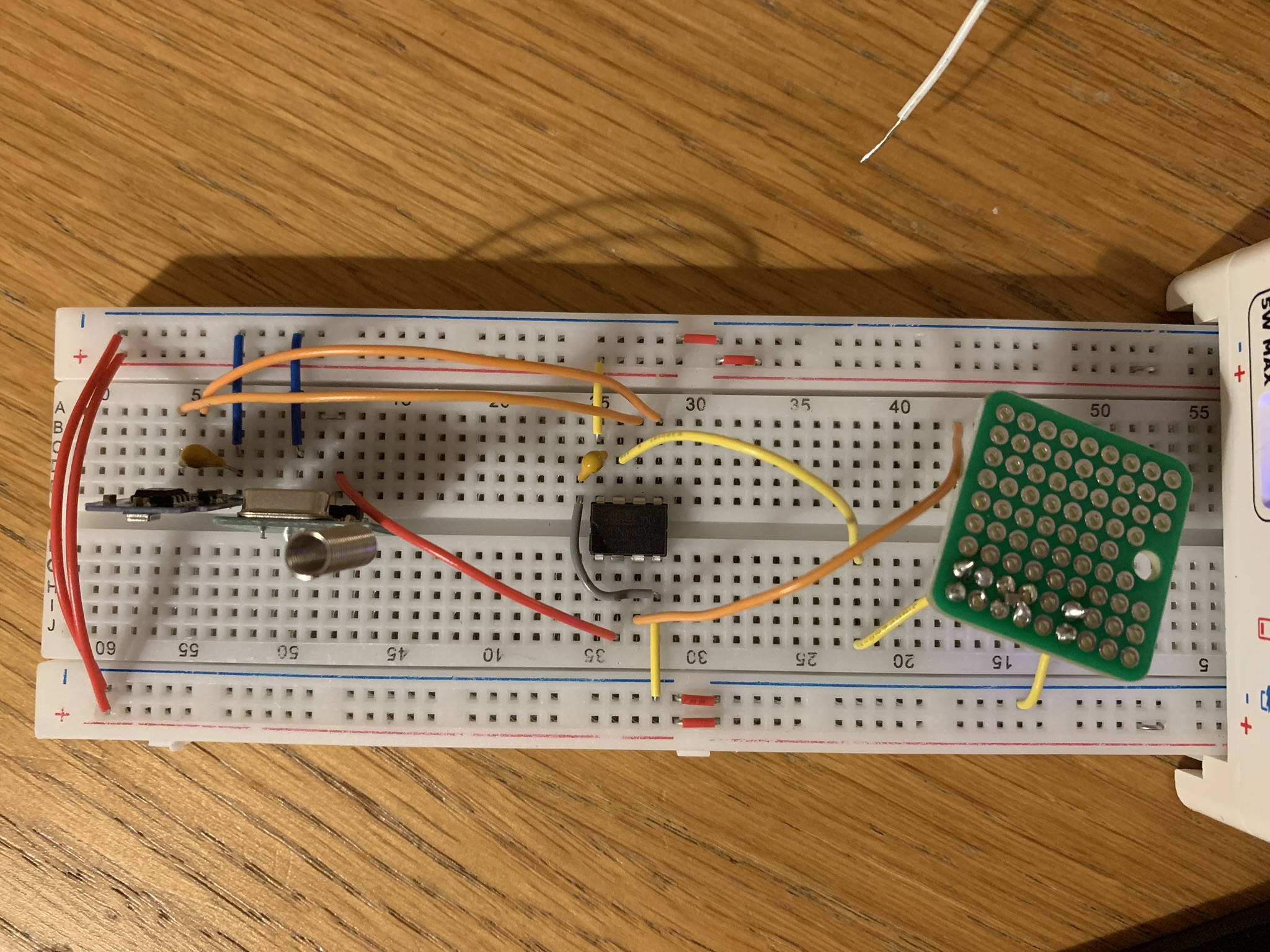
Converting my v2 prototype into the final build was in principle straightforward, but took a lot of work. I planned out a circuit to connect the microcontroller pins to the radio, sensor, and oscillator as described in the code, then soldered it all together. Note the 100 nF capacitors connected between power and ground of the ATtiny85 and the DHT22: these are to decouple the chips from the power supply.
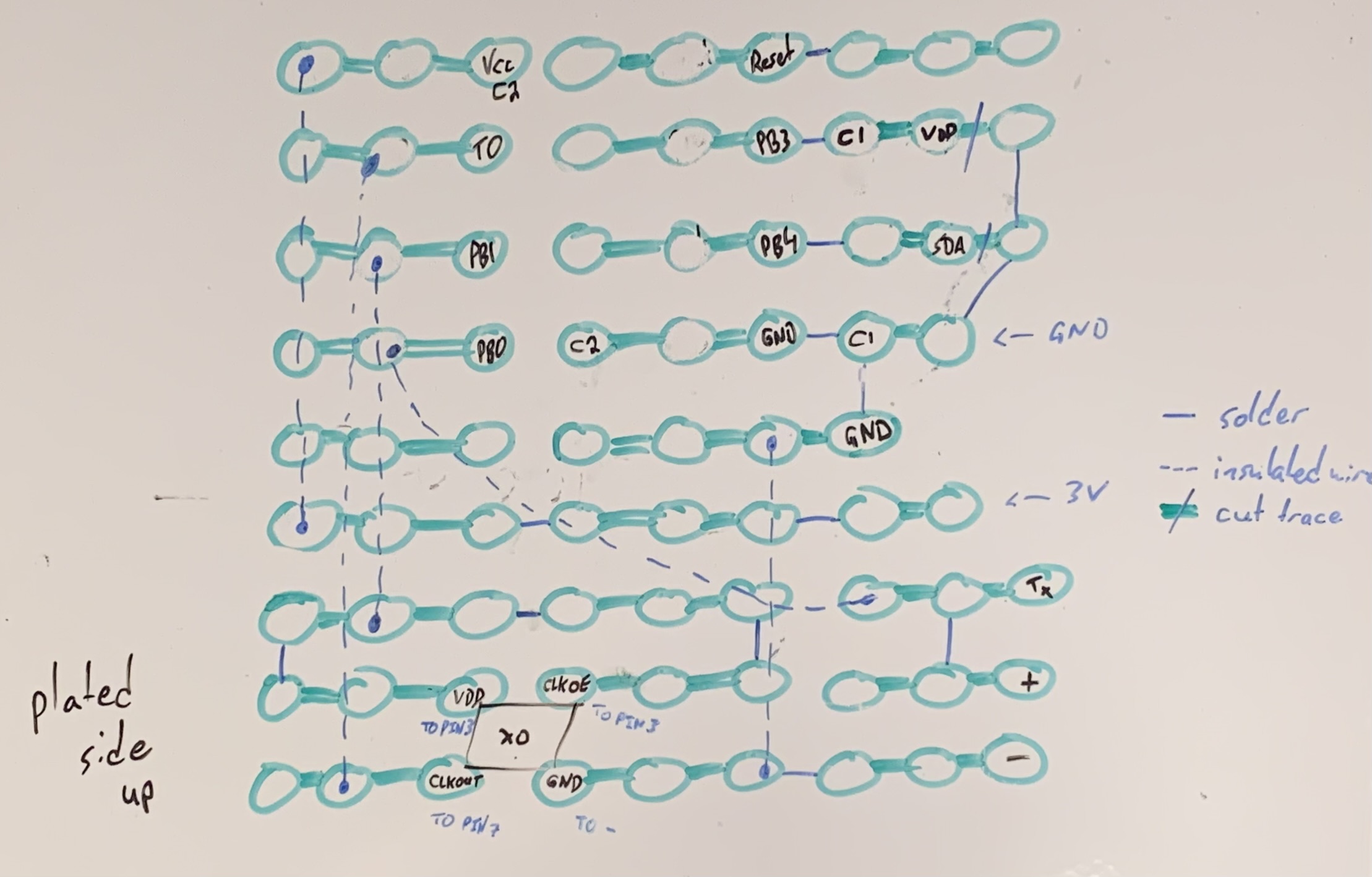
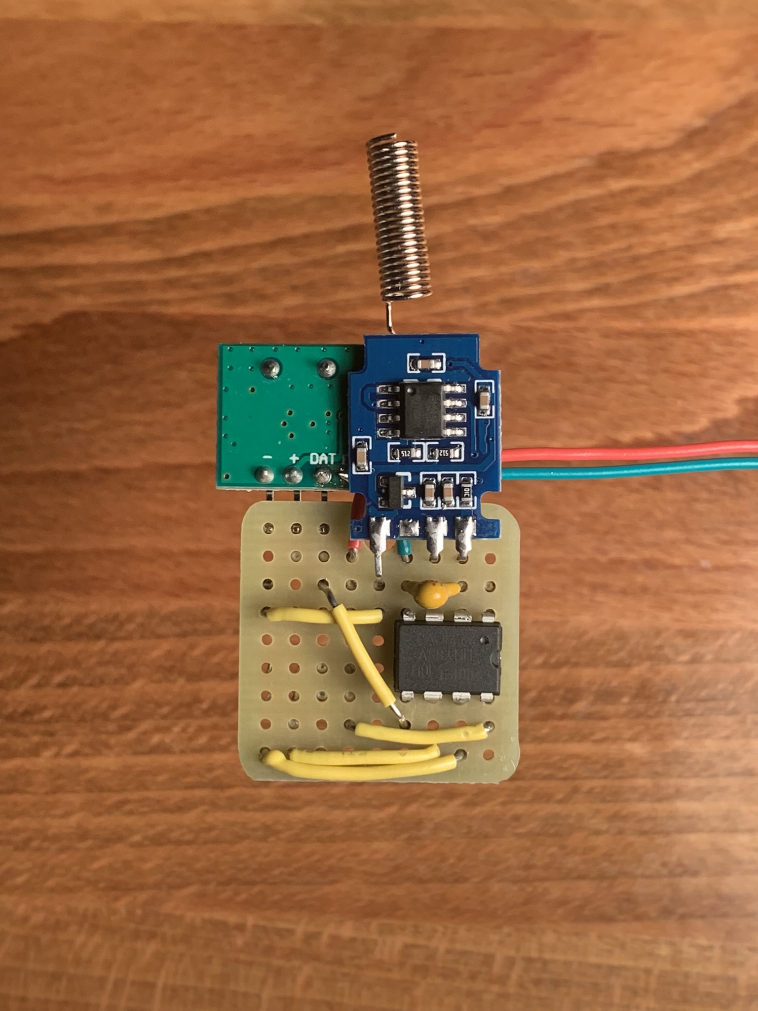
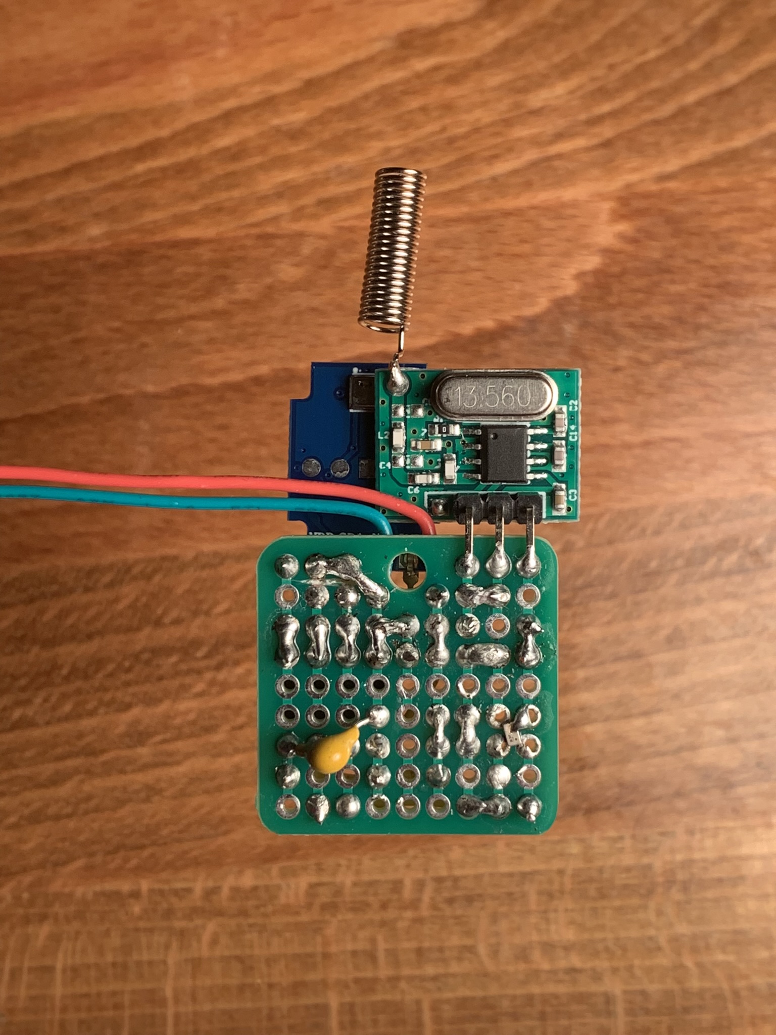
All of the components I selected are pretty flexible in terms of what voltages they’ll operate on. As a result, this circuit can be powered by either two or three AAA or AA cells, depending on the desired battery life and signal power. A device reset/channel change can be triggered by using a metal screwdriver to briefly connect the reset pin and ground (i.e. the top-left-most two blobs in the last picture).
Code
Also hosted on GitHub, here. The code below is up-to-date only as of the initial commit in the linked repo.
sensor.ino
1
/*
2
* ATtiny85-based temperature/humidity sensor compatible with the Oregon Scientific v2.1
3
* 433.92 MHz weather sensor protocol.
4
*
5
* This sketch replicates the behaviour of the Oregon Scientific THGR122NX sensor.
6
*
7
* Most of the pin assignments defined below are flexible; the only one that isn't is T0,
8
* which must be connected to the external oscillator clocking Timer/Counter0. On the
9
* ATtiny85, T0 is on PB2.
10
*
11
* More info here: https://shumphries.ca/blog/2023/01/03/oregon-scientific-attiny85
12
*
13
* LICENCE
14
*
15
* Copyright © 2023 Stephen Humphries
16
*
17
* Permission is hereby granted, free of charge, to any person obtaining a copy
18
* of this software and associated documentation files (the "Software"), to deal
19
* in the Software without restriction, including without limitation the rights
20
* to use, copy, modify, merge, publish, distribute, sublicense, and/or sell
21
* copies of the Software, and to permit persons to whom the Software is
22
* furnished to do so, subject to the following conditions:
23
*
24
* The above copyright notice and this permission notice shall be included in all
25
* copies or substantial portions of the Software.
26
*
27
* THE SOFTWARE IS PROVIDED "AS IS", WITHOUT WARRANTY OF ANY KIND, EXPRESS OR
28
* IMPLIED, INCLUDING BUT NOT LIMITED TO THE WARRANTIES OF MERCHANTABILITY,
29
* FITNESS FOR A PARTICULAR PURPOSE AND NONINFRINGEMENT. IN NO EVENT SHALL THE
30
* AUTHORS OR COPYRIGHT HOLDERS BE LIABLE FOR ANY CLAIM, DAMAGES OR OTHER
31
* LIABILITY, WHETHER IN AN ACTION OF CONTRACT, TORT OR OTHERWISE, ARISING FROM,
32
* OUT OF OR IN CONNECTION WITH THE SOFTWARE OR THE USE OR OTHER DEALINGS IN THE
33
* SOFTWARE.
34
*/
35
36
#include <avr/sleep.h>
37
#include <avr/wdt.h>
38
39
#include "DHTWrapper.h"
40
#define DHT_DATA_PIN 4 // I/O for the temperature/humidity sensor
41
#define DHT_POWER_PIN 3
42
DHTWrapper dht = DHTWrapper(DHT_DATA_PIN, DHT_POWER_PIN);
43
44
#define T0_PIN 2
45
#define T0_XO_POWER_PIN 1 // Power for the crystal oscillator clocking Timer0
46
#include "OS21Tx.h"
47
#define TX_PIN 0 // Output for the 433.92 Mhz modulator
48
OS21Tx tx = OS21Tx(TX_PIN);
49
50
#include <EEPROM.h>
51
#define RESET_COUNT_ADDR 0 // Where to store the current reset count (used for seeding RNG and saving channel setting)
52
53
#define RESET_PIN 5
54
55
#define LOW_BATTERY 2000 // Threshold in mV (2V picked with 2x 1.5V AAA cells in mind. Adjust as required.)
56
57
void setup() {
58
cli();
59
uint8_t _MCUSR = MCUSR;
60
MCUSR = 0; // As per the datasheet, if a watchdog timer reset status flag is set, it must be cleared ASAP
61
wdt_disable(); // Otherwise, the watchdog timer will start over immediately with the smallest prescale value
62
sei();
63
64
ADCSRA = 0; // Disable Analog to Digital Converter (wastes power)
65
66
pinMode(RESET_PIN, INPUT_PULLUP); // Leaving the reset pin floating can trigger random resets
67
68
pinMode(T0_XO_POWER_PIN, OUTPUT);
69
70
uint32_t resetCount;
71
EEPROM.get(RESET_COUNT_ADDR, resetCount);
72
if (_MCUSR & (1 << EXTRF)) { // Increment the saved channel if an external reset was triggered
73
++resetCount;
74
EEPROM.put(RESET_COUNT_ADDR, resetCount);
75
}
76
77
uint8_t channel = (resetCount % 3) + 1; // i.e. 1, 2, or 3
78
randomSeed(resetCount); // Seed RNG for picking Rolling ID
79
80
dht.begin();
81
tx.begin(channel, random(256));
82
}
83
84
void loop() {
85
digitalWrite(T0_XO_POWER_PIN, HIGH);
86
dht.powerOn();
87
88
// Sleep for 2 seconds to give the DHT22 and crystal oscillator a chance to wake up
89
set_sleep_mode(SLEEP_MODE_PWR_DOWN);
90
sleep_enable();
91
WDTCR = (1 << WDIE) | (1 << WDCE) | (1 << WDE) | (1 << WDP2) | (1 << WDP1) | (1 << WDP0); // Enable watchdog timer interrupt with 2 second countdown (see ATtiny85 datasheet, section 8.5)
92
wdt_reset(); // With the WDE bit set, too, WDIE is cleared when a timeout occurs, putting the watchdog in reset mode
93
sleep_cpu(); // So if something in the following sensor or tx code hangs for more than 2s, the watchdog will trigger a chip reset
94
sleep_disable();
95
96
float t, h;
97
dht.read(t, h);
98
99
if (dht.irrationalReading(t, h)) {
100
return; // Try again if we get a known bad reading
101
}
102
103
dht.powerOff();
104
105
#ifdef LOW_BATTERY
106
tx.transmit(t, h, getVcc() < LOW_BATTERY);
107
#else
108
tx.transmit(t, h);
109
#endif
110
111
digitalWrite(T0_XO_POWER_PIN, LOW);
112
113
// Sleep for 8*5 = 40 seconds (8 seconds is the max for the watchdog timer prescaler)
114
set_sleep_mode(SLEEP_MODE_PWR_DOWN);
115
sleep_enable();
116
wdt_disable(); // Clear WDE to put watchdog timer back in interrupt-only mode
117
WDTCR = (1 << WDIE) | (1 << WDCE) | (1 << WDP3) | (1 << WDP0);
118
wdt_reset();
119
sleep_cpu(); // This is probably overly cautious, but I'm not using a loop here
120
sleep_cpu(); // because if cosmic rays or something disrupted the counter, we
121
sleep_cpu(); // could be sleeping for a very long time, since the watchdog timer
122
sleep_cpu(); // reset is disabled at this point
123
sleep_cpu();
124
sleep_disable();
125
}
126
127
ISR(WDT_vect) {
128
// Interrupt handler for watchdog timer
129
// Do nothing; just return control flow to where it was before sleeping
130
}
131
132
long getVcc() {
133
uint8_t _ADCSRA = ADCSRA;
134
135
ADCSRA = (1 << ADEN); // Enable ADC
136
ADMUX = (1 << MUX3) | (1 << MUX2); // Vcc as voltage reference; 1.1V bandgap voltage as measurement target
137
138
delay(2); // Allow ADC to settle after switching to internal voltage reference (as per datasheet)
139
140
ADCSRA |= (1 << ADSC); // Start conversion
141
while (ADCSRA & (1 << ADSC));
142
143
uint8_t adcl = ADCL;
144
uint8_t adch = ADCH;
145
146
uint16_t result = (adch << 8) | (adcl << 0); // result is 10 bits (max 1023)
147
148
ADCSRA = _ADCSRA;
149
150
return 1125300L / result; // Vcc in mV (1.1 * 1023 * 1000 = 1125300)
151
}
DHTWrapper.h
1
/*
2
* A fairly dumb wrapper for DHT.h that adds handling for powering a DHT22 sensor
3
* on and off via a separate power pin.
4
5
* More info here: https://shumphries.ca/blog/2023/01/03/oregon-scientific-attiny85
6
*
7
* LICENCE
8
*
9
* Copyright © 2023 Stephen Humphries
10
*
11
* Permission is hereby granted, free of charge, to any person obtaining a copy
12
* of this software and associated documentation files (the "Software"), to deal
13
* in the Software without restriction, including without limitation the rights
14
* to use, copy, modify, merge, publish, distribute, sublicense, and/or sell
15
* copies of the Software, and to permit persons to whom the Software is
16
* furnished to do so, subject to the following conditions:
17
*
18
* The above copyright notice and this permission notice shall be included in all
19
* copies or substantial portions of the Software.
20
*
21
* THE SOFTWARE IS PROVIDED "AS IS", WITHOUT WARRANTY OF ANY KIND, EXPRESS OR
22
* IMPLIED, INCLUDING BUT NOT LIMITED TO THE WARRANTIES OF MERCHANTABILITY,
23
* FITNESS FOR A PARTICULAR PURPOSE AND NONINFRINGEMENT. IN NO EVENT SHALL THE
24
* AUTHORS OR COPYRIGHT HOLDERS BE LIABLE FOR ANY CLAIM, DAMAGES OR OTHER
25
* LIABILITY, WHETHER IN AN ACTION OF CONTRACT, TORT OR OTHERWISE, ARISING FROM,
26
* OUT OF OR IN CONNECTION WITH THE SOFTWARE OR THE USE OR OTHER DEALINGS IN THE
27
* SOFTWARE.
28
*/
29
30
#ifndef DHTWRAPPER_H
31
#define DHTWRAPPER_H
32
33
#include <DHT.h> // Adafruit's DHT sensor library (https://github.com/adafruit/DHT-sensor-library)
34
35
#define SENSOR_TYPE DHT22
36
37
class DHTWrapper {
38
public:
39
const uint8_t dataPin;
40
const uint8_t powerPin;
41
DHT dht;
42
43
DHTWrapper(uint8_t dataPin, uint8_t powerPin): dataPin(dataPin), powerPin(powerPin), dht(DHT(dataPin, SENSOR_TYPE)) {}
44
45
void begin() {
46
pinMode(powerPin, OUTPUT);
47
dht.begin(); // Must call this to set the initial pulltime value (see dht.h/dht.cpp)
48
pinMode(dataPin, OUTPUT);
49
digitalWrite(dataPin, LOW);
50
}
51
52
void powerOn() {
53
digitalWrite(powerPin, HIGH);
54
// DHT::read() takes care of setting the data pin to the correct state before reading
55
}
56
57
void powerOff() {
58
digitalWrite(powerPin, LOW);
59
60
pinMode(dataPin, OUTPUT);
61
digitalWrite(dataPin, LOW);
62
}
63
64
void read(float &t, float &h) {
65
// Without force=true, the DHT library only communicates with the seonsor if the last reading was taken more than 2 seconds ago
66
// Since power off sleeping stops all the clocks, that 2 seconds would be counting actual CPU run time, which is not helpful for this application
67
t = dht.readTemperature(/*fahrenheit*/false, /*force*/true);
68
h = dht.readHumidity(/*force*/false);
69
}
70
71
bool irrationalReading(float t, float h) {
72
return (
73
(t == 0.0 && h == 0.0) || // Returned by DHT::read() when the reading times out; rare if the sensor is given long enough to power on, but still possible
74
(t == 150.0 && h == 100.0) || // My sensor seems to sometimes return irrational data pairs like this and the next one. Maybe it's a bad part ¯\_(ツ)_/¯
75
(t == 50.0 && h == 0.0)
76
);
77
}
78
};
79
80
#endif /* DHTWRAPPER_H */
OS21Tx.h
1
/*
2
* A library for transmitting temperature and humidity data via the Oregon Scientific v2.1 protocol.
3
*
4
* Requires a 433.92 MHz transmitter connected to a digital pin and a 32 768 Hz crystal oscillator
5
* connected to T0 (PB2 on ATtiny85).
6
*
7
* Assumes that an interrupt waking the CPU from sleep will occur 2 048 times per second. It should
8
* be straightforward to change how this interrupt is generated (e.g. to use an oscillator with a
9
* different frequency) by modifying the configureTimer() and restoreTimer() functions below.
10
11
* More info here: https://shumphries.ca/blog/2023/01/03/oregon-scientific-attiny85
12
*
13
* LICENCE
14
*
15
* Copyright © 2023 Stephen Humphries
16
*
17
* Permission is hereby granted, free of charge, to any person obtaining a copy
18
* of this software and associated documentation files (the "Software"), to deal
19
* in the Software without restriction, including without limitation the rights
20
* to use, copy, modify, merge, publish, distribute, sublicense, and/or sell
21
* copies of the Software, and to permit persons to whom the Software is
22
* furnished to do so, subject to the following conditions:
23
*
24
* The above copyright notice and this permission notice shall be included in all
25
* copies or substantial portions of the Software.
26
*
27
* THE SOFTWARE IS PROVIDED "AS IS", WITHOUT WARRANTY OF ANY KIND, EXPRESS OR
28
* IMPLIED, INCLUDING BUT NOT LIMITED TO THE WARRANTIES OF MERCHANTABILITY,
29
* FITNESS FOR A PARTICULAR PURPOSE AND NONINFRINGEMENT. IN NO EVENT SHALL THE
30
* AUTHORS OR COPYRIGHT HOLDERS BE LIABLE FOR ANY CLAIM, DAMAGES OR OTHER
31
* LIABILITY, WHETHER IN AN ACTION OF CONTRACT, TORT OR OTHERWISE, ARISING FROM,
32
* OUT OF OR IN CONNECTION WITH THE SOFTWARE OR THE USE OR OTHER DEALINGS IN THE
33
* SOFTWARE.
34
*/
35
36
#ifndef OS21TX_H
37
#define OS21TX_H
38
39
// Example transmission data
40
// - Bytes are transmitted in order, small nibble first
41
// - Nibbles are transmitted LSB-first
42
// - Nibble descritions in this example are large nibble first, to align with the byte-wise representation
43
// - Sensor ID 1d20, Channel 1, Rolling ID bb, Battery low, Temperature 22.7°C, Humidity 30%
44
// uint8_t data[] = {
45
// 0xff, // Preamble (16 ones (transmitted as 32 bits, alternating 01))
46
// 0xff, // Preamble
47
// 0x1a, // Sensor ID (1d20) / Sync (0xa)
48
// 0x2d, // Sensor ID
49
// 0x20, // Channel (1=0x1, 2=0x2, 3=0x4) / Sensor ID
50
// 0xbb, // Rolling ID (randomly generated on startup)
51
// 0x7c, // Temperature, 10^-1 / Battery low (low is 0x4, not low is 0x0, but both are often OR'd with a 0x8 bit of unknown significance)
52
// 0x22, // Temperature, 10^1 / Temperature, 10^0
53
// 0x00, // Humidity, 10^0 / Temperature sign (largest 2 bits, 0x0 for +ve, 0x8 for -ve) | Temperature 10^2 (smallest 2 bits)
54
// 0x83, // Unknown / Humidity, 10^1
55
// 0x4a, // Checksum (simple sum)
56
// 0x55, // Postamble (CRC checksum)
57
// };
58
59
#define SUM_MASK 0xfffe0 // Only some nibbles are included in the checksum and CRC calculations
60
#define CRC_MASK 0xff3e0
61
#define CRC_IV 0x42 // ¯\_(ツ)_/¯ (see the blog post for details)
62
#define CRC_POLY 0x7 // CRC-8-CCITT
63
64
#define DATA_LEN 12
65
66
#include <avr/sleep.h>
67
68
class OS21Tx {
69
public:
70
const uint8_t pin;
71
72
OS21Tx(uint8_t pin): pin(pin) {}
73
74
void begin(uint8_t channel, uint8_t rollingId) {
75
pinMode(pin, OUTPUT);
76
77
setRollingId(rollingId);
78
setChannel(channel);
79
}
80
81
void transmit(float temperature, float humidity, bool lowBattery = false) {
82
setTemperature(temperature);
83
setHumidity(humidity);
84
setLowBattery(lowBattery);
85
setChecksum();
86
setCRC();
87
88
sendData(); // Send the message twice
89
delay(55); // Pause for a short time between transmissions
90
sendData();
91
}
92
93
private:
94
95
uint8_t old_TCCR0A;
96
uint8_t old_TCCR0B;
97
uint8_t old_OCR0A;
98
uint8_t old_TIMSK;
99
100
uint8_t data[DATA_LEN] = { // Data frame, initialized with the parts that never change
101
0xff, // Preamble
102
0xff,
103
0x1a, // Sync nibble and sensor ID
104
0x2d,
105
0x00,
106
0x00,
107
0x08, // Unknown
108
0x00,
109
0x00,
110
0x80, // Unknown
111
0x00,
112
0x00,
113
};
114
115
void setRollingId(uint8_t rollingId) {
116
data[5] &= 0x00; data[5] |= (rollingId & 0xff);
117
}
118
119
void setChannel(uint8_t channel) {
120
const uint8_t channelCode = (1 << (channel - 1)); // 1=0x1, 2=0x2, 3=0x4
121
data[4] &= 0x0f; data[4] |= ((channelCode << 4) & 0xf0);
122
}
123
124
void setTemperature(float t) {
125
const uint8_t t_sign = t < 0;
126
const uint8_t t_deci = ((int)(t * (t_sign ? -10 : 10)) / 1) % 10;
127
const uint8_t t_ones = ((int)(t * (t_sign ? -10 : 10)) / 10) % 10;
128
const uint8_t t_tens = ((int)(t * (t_sign ? -10 : 10)) / 100) % 10;
129
const uint8_t t_huns = ((int)(t * (t_sign ? -10 : 10)) / 1000) % 10;
130
131
data[6] &= 0x0f; data[6] |= ((t_deci << 4) & 0xf0);
132
data[7] &= 0xf0; data[7] |= ((t_ones << 0) & 0x0f);
133
data[7] &= 0x0f; data[7] |= ((t_tens << 4) & 0xf0);
134
data[8] &= 0xfc; data[8] |= ((t_huns << 0) & 0x03);
135
data[8] &= 0xf3; data[8] |= ((t_sign << 3) & 0x0c);
136
}
137
138
void setHumidity(float h) {
139
h += 0.5; // Round to the nearest one by adding 0.5 then truncating the decimal
140
141
const uint8_t h_ones = ((int)(h * 10) / 10) % 10;
142
const uint8_t h_tens = ((int)(h * 10) / 100) % 10;
143
144
data[8] &= 0x0f; data[8] |= ((h_ones << 4) & 0xf0);
145
data[9] &= 0xf0; data[9] |= ((h_tens << 0) & 0x0f);
146
}
147
148
void setLowBattery(bool b) {
149
data[6] &= 0xf8; data[6] |= (b ? 0x4 : 0x0);
150
}
151
152
void setChecksum() {
153
data[10] &= 0x00; data[10] |= (checksumSimple(data, SUM_MASK) & 0xff);
154
}
155
156
void setCRC() {
157
data[11] &= 0x00; data[11] |= (checksumCRC(data, CRC_MASK, CRC_IV) & 0xff);
158
}
159
160
void sendData() {
161
configureTimer();
162
163
for (int i = 0; i < DATA_LEN * 8; ++i) { // Bits are transmitted LSB-first
164
sendBit((data[i / 8] >> (i % 8)) & 0x1);
165
}
166
writeSyncBit(LOW); // Don't leave the transmitter on!
167
168
restoreTimer();
169
}
170
171
void sendBit(bool val) {
172
if (val) {
173
sendZero(); // Recall that each bit is sent twice, inverted first
174
sendOne();
175
} else {
176
sendOne();
177
sendZero();
178
}
179
}
180
181
void sendZero() {
182
writeSyncBit(LOW);
183
writeSyncBit(HIGH);
184
}
185
186
void sendOne() {
187
writeSyncBit(HIGH);
188
writeSyncBit(LOW);
189
}
190
191
static uint8_t checksumSimple(const uint8_t data[], uint64_t mask) {
192
uint16_t s = 0x0000;
193
194
for (int i = 0; i < 64; ++i) {
195
if (!((mask >> i) & 0x1)) continue; // Skip nibbles that aren't set in the mask
196
197
s += (data[i / 2] >> ((i % 2) * 4)) & 0xf; // Sum data nibble by nibble
198
s += (s >> 8) & 0x1; // Add any overflow back into the sum
199
s &= 0xff;
200
}
201
202
return s;
203
}
204
205
206
static uint8_t checksumCRC(const uint8_t data[], uint64_t mask, uint8_t iv) {
207
uint16_t s = iv;
208
209
for (int i = 0; i < 64; ++i) {
210
if (!((mask >> i) & 0x1)) continue; // Skip nibbles that aren't set in the mask
211
212
uint8_t nibble = (data[i / 2] >> ((i % 2) * 4)) & 0xf;
213
214
for (int j = 3; j >= 0; --j) {
215
uint8_t bit = (nibble >> j) & 0x1;
216
217
s <<= 1;
218
s |= bit;
219
220
if (s & 0x100) {
221
s ^= CRC_POLY;
222
}
223
}
224
}
225
226
for (int i = 0; i < 8; ++i) {
227
s <<= 1;
228
if (s & 0x100) {
229
s ^= CRC_POLY;
230
}
231
}
232
233
return s;
234
}
235
236
void writeSyncBit(bool val) {
237
// Synchronise writes to the 2048 Hz timer by sleeping until the timer interrupt
238
// This works so long as there's less than 488 us worth of computation between write calls
239
sleep_cpu(); // Sleep right before a pin change (rather than after) to ensure all edges are identically spaced
240
digitalWrite(pin, val);
241
}
242
243
void configureTimer() {
244
old_TCCR0A = TCCR0A; // Save and restore Timer0 config since it's used by Arduino for delay()
245
old_TCCR0B = TCCR0B;
246
old_OCR0A = OCR0A;
247
old_TIMSK = TIMSK;
248
249
cli();
250
TCCR0A = (1 << WGM01); // CTC (Clear Timer on Compare Match)
251
TCCR0B = (1 << CS02) | (1 << CS01) | (1 << CS00); // External clock source on T0 pin
252
OCR0A = 0xf; // Output compare register (32 768 Hz / 16 = 2 048 Hz)
253
TIMSK = (1 << OCIE0A); // Interrupt on output compare match
254
sei();
255
256
set_sleep_mode(SLEEP_MODE_IDLE);
257
sleep_enable();
258
}
259
260
void restoreTimer() {
261
sleep_disable();
262
263
cli();
264
TCCR0A = old_TCCR0A;
265
TCCR0B = old_TCCR0B;
266
OCR0A = old_OCR0A;
267
TIMSK = old_TIMSK;
268
sei();
269
}
270
};
271
272
ISR(TIMER0_COMPA_vect) {
273
// Interrupt handler for TIMER0
274
// Do nothing; just return control flow to where it was before sleeping
275
}
276
277
#endif /* OS21TX_H */